Convert old ethernet shield to an SDCard compatible version
I had the need to find some more storage space for a project I'm working on. I really would like to use the SD card that now comes with the new ethernet shield, but I had no time to order one and wait for it to arrive. So I noticed that the old shield actually has a space to put an SDCard but the area is empty. Also, although there are obvious differences, the shields look pretty much the same. All of that led me to believe that there was a way to add an SDcard to the old ethernet shield version and convert it in terms of operation onto the new version. This is a short description about how I went on to do just that.


First thing to do is to pull out the schematics for each of these cards and actually look for the differences:
old version
new version
The parts on the schematics that are of interest to us at the moment are the following:


pin4 (Vdd) ----- to the 3.3V feed from the arduino
pin5 (CLK)* ----- to the SCK signal (i.e. to D13/ SPI SCK on the arduino)
pin6 (Vss) ----- GND
pin7 (DAT0/DO) ----- direct to the MISO (D12) signal on the arduino
pin8 ----- not connected
Above note the 3 items with a * after them. that means that the connection is not direct to the arduino pins but it's fed through a voltage divider. This is simply because the SDCard logic is at 3.3V while the arduino's is at 5V, so we need to convert from one to the other and the voltage divider is an efficient and cheap way of achieving it (just for fun, you can verify through the voltage divider equation Vout = R2/(R2+R1)*Vin, if you make R2 = 2K2, R1 = 1K and Vin = 5V, then Vout = 3.4V which is the levels we need to work at).
So we also know that we need to add these voltage dividers to our external circuit. What confused me for a bit was the direct connection of the MISO line (D12) to the arduino. Originally I assumed I wasn't reading the schematics properly and actually connected a fourth voltage divider for that line. Well, it doesn't work! It has to be direct (any ideas?)
So I went ahead and built all of what I just described on a breadboard. As I also mentioned I pulled a microSD card slot from an old camera I had and soldered leads to each pin and then took the leads to the breadboard and connected the voltage divider and the arduino to it.
My test setup looks like this:
 To make it work now without writing all your code from scratch, you need to use the sdfatlib that you can download from here. The better option after building the hardware is to follow this tutorial to get it to work (EDIT: this one is also helpful).
BUUUUUUUUUUUUT things are never this easy and now we come to the other problem (besides overall connections as described) that does not allow us to properly use the card (or any other SPI peripheral for that matter) with the old ethernet card. It all has to do with a hardware bug (may I call it a bug?) on the wiznet chip that comes with the shield. That chip is described as a SPI device but it doesn't do something just quite well: it does not release the SPI bus even if its CS (chip select) pin is telling it to do it. So you can't speak to anything else on the SPI bus... or can't you? Well, you can but you need to make a little change:
Sometime in the past Wiznet published some application notes on the wiznet ethernet chip (you can read that doc here) where it stated that:
"Multiple SPI Slave Usage
Basically, multiple SPI slave usage is the same as single SPI slave usage. One difference between other SPI slave devices compared to the W5100 is that the MISO output is continuously driven in the W5100 whether the /SCS is asserted as high or as low. As well, when the 5100 /SCS is asserted as high when using multiple slaves, other SPI devices cannot be read or written by the SPI master on the SPI BUS simultaneously. These problems will continue unless the recommendations listed below are followed.
Recommendations:
- When accessing another device on the SPI BUS rather than the W5100, assert the SEN pin in the W5100 as low first, then access the other devices.
- When accessing the W5100, the SEN pin should be high."
So besides the CS signal, we need to implement another that is basically the inverse of the CS line. This other line is the SEN line as stated in the text above. Hum, but where can we have access to the SEN line? looking at the schematics we can see that that line appears on the PROG jumper, pin2 (see the bottom left corner of the schematics).
So, to control that SEN signal along with the CS signal (already implemented, we need only to choose a free output from the arduino and connect it to PROG jumper, pin2 and therefore to the SEN line. I chose to connect it to D7 and I soldered a jumper wire under the ethernet shield board connecting these two points. Any selection/ deselection of the ethernet chip now becomes:
//enable the ethernet chip on the SPI bus
void EtherSelect(){
digitalWrite(ETHER_CS, LOW);
digitalWrite(ETHER_SEL, HIGH);
}
//disable the ethernet chip on the SPI bus
void EtherDeselect(){
digitalWrite(ETHER_CS, HIGH);
digitalWrite(ETHER_SEL, LOW);
}
where ETHER_CS is pin10 (see schematics) and ETHER_SEL is pin 7 as I described above.
I know that the description above may seem a little confusing but it is very rewarding to have it working without having to buy a new shield.
All the best with your projects!
EDIT (7th May 2011): See my comment for this post for additional information.

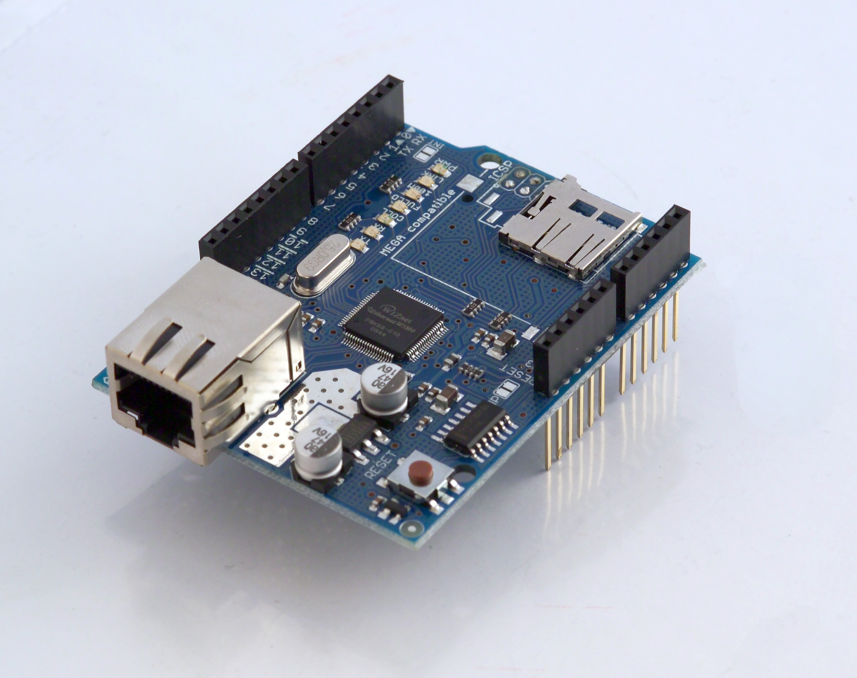
The old ethernet card. Note the solder points on the top but no SDCard slot in there! Begging for an upgrade!
The new ethernet card version with a microSD card slot installed.
First thing to do is to pull out the schematics for each of these cards and actually look for the differences:
old version
new version
The parts on the schematics that are of interest to us at the moment are the following:
for the old card (click the image to enlarge)

for the new card (click the image to enlarge)
First thing we note is that the DETECT, COM_TERM and WRITE_PROT circuits are the same. Everything else is pretty much different... so we have our first conclusion: thre will be no direct soldering of an SDCard slot on to the old board.
Ok, so it will not look nice and beautiful anymore but perhaps it can still work by simply copying the connections on the new board direct from an SDcard slot to the board headers. First thing to do then is to confirm the microSD card pinout. I simply used this image that I found on google images (from this website, another cool description to get the SDCard to work with an Atmega168):

Because I had a microSD card slot on an old device that I could de-solder out and because we can easily communicate with the card via SPI, I was interested on the bottom picture and the SPI column pinout. Cross checking this information with the new ethernet card schematics we can see that:
SDcard ----- Arduino
pin1 ----- not connected
pin2 (CD/DAT3)* ----- to the SD_CS signal (i.e. to J2, pin5 corresponds to D4 on the arduino)
pin3 (CMD/DI)* ----- to the MOSI3 signal (i.e. to D11/ SPI MOSI on the arduino)pin4 (Vdd) ----- to the 3.3V feed from the arduino
pin5 (CLK)* ----- to the SCK signal (i.e. to D13/ SPI SCK on the arduino)
pin6 (Vss) ----- GND
pin7 (DAT0/DO) ----- direct to the MISO (D12) signal on the arduino
pin8 ----- not connected
Above note the 3 items with a * after them. that means that the connection is not direct to the arduino pins but it's fed through a voltage divider. This is simply because the SDCard logic is at 3.3V while the arduino's is at 5V, so we need to convert from one to the other and the voltage divider is an efficient and cheap way of achieving it (just for fun, you can verify through the voltage divider equation Vout = R2/(R2+R1)*Vin, if you make R2 = 2K2, R1 = 1K and Vin = 5V, then Vout = 3.4V which is the levels we need to work at).
So we also know that we need to add these voltage dividers to our external circuit. What confused me for a bit was the direct connection of the MISO line (D12) to the arduino. Originally I assumed I wasn't reading the schematics properly and actually connected a fourth voltage divider for that line. Well, it doesn't work! It has to be direct (any ideas?)
So I went ahead and built all of what I just described on a breadboard. As I also mentioned I pulled a microSD card slot from an old camera I had and soldered leads to each pin and then took the leads to the breadboard and connected the voltage divider and the arduino to it.
My test setup looks like this:

BUUUUUUUUUUUUT things are never this easy and now we come to the other problem (besides overall connections as described) that does not allow us to properly use the card (or any other SPI peripheral for that matter) with the old ethernet card. It all has to do with a hardware bug (may I call it a bug?) on the wiznet chip that comes with the shield. That chip is described as a SPI device but it doesn't do something just quite well: it does not release the SPI bus even if its CS (chip select) pin is telling it to do it. So you can't speak to anything else on the SPI bus... or can't you? Well, you can but you need to make a little change:
Sometime in the past Wiznet published some application notes on the wiznet ethernet chip (you can read that doc here) where it stated that:
"Multiple SPI Slave Usage
Basically, multiple SPI slave usage is the same as single SPI slave usage. One difference between other SPI slave devices compared to the W5100 is that the MISO output is continuously driven in the W5100 whether the /SCS is asserted as high or as low. As well, when the 5100 /SCS is asserted as high when using multiple slaves, other SPI devices cannot be read or written by the SPI master on the SPI BUS simultaneously. These problems will continue unless the recommendations listed below are followed.
Recommendations:
- When accessing another device on the SPI BUS rather than the W5100, assert the SEN pin in the W5100 as low first, then access the other devices.
- When accessing the W5100, the SEN pin should be high."
So besides the CS signal, we need to implement another that is basically the inverse of the CS line. This other line is the SEN line as stated in the text above. Hum, but where can we have access to the SEN line? looking at the schematics we can see that that line appears on the PROG jumper, pin2 (see the bottom left corner of the schematics).
So, to control that SEN signal along with the CS signal (already implemented, we need only to choose a free output from the arduino and connect it to PROG jumper, pin2 and therefore to the SEN line. I chose to connect it to D7 and I soldered a jumper wire under the ethernet shield board connecting these two points. Any selection/ deselection of the ethernet chip now becomes:
//enable the ethernet chip on the SPI bus
void EtherSelect(){
digitalWrite(ETHER_CS, LOW);
digitalWrite(ETHER_SEL, HIGH);
}
//disable the ethernet chip on the SPI bus
void EtherDeselect(){
digitalWrite(ETHER_CS, HIGH);
digitalWrite(ETHER_SEL, LOW);
}
where ETHER_CS is pin10 (see schematics) and ETHER_SEL is pin 7 as I described above.
I know that the description above may seem a little confusing but it is very rewarding to have it working without having to buy a new shield.
All the best with your projects!
EDIT (7th May 2011): See my comment for this post for additional information.
Comments
/*
SD card basic file example
This example shows how to create and destroy an SD card file
The circuit:
* SD card attached to SPI bus as follows:
** MOSI - pin 11
** MISO - pin 12
** CLK - pin 13
** CS - pin 4
created Nov 2010
by David A. Mellis
updated 2 Dec 2010
by Tom Igoe
This example code is in the public domain.
*/
#include
File myFile;
void setup()
{
Serial.begin(9600);
Serial.print("Initializing SD card...");
// On the Ethernet Shield, CS is pin 4. It's set as an output by default.
// Note that even if it's not used as the CS pin, the hardware SS pin
// (10 on most Arduino boards, 53 on the Mega) must be left as an output
// or the SD library functions will not work.
pinMode(10, OUTPUT);
pinMode(7, OUTPUT);
digitalWrite(10, HIGH);
digitalWrite(7, LOW);
if (!SD.begin(4)) {
Serial.println("initialization failed!");
return;
}
Serial.println("initialization done.");
if (SD.exists("example.txt")) {
Serial.println("example.txt exists.");
}
else {
Serial.println("example.txt doesn't exist.");
}
// open a new file and immediately close it:
Serial.println("Creating example.txt...");
myFile = SD.open("example.txt", FILE_WRITE);
myFile.close();
// Check to see if the file exists:
if (SD.exists("example.txt")) {
Serial.println("example.txt exists.");
}
else {
Serial.println("example.txt doesn't exist.");
}
// delete the file:
Serial.println("Removing example.txt...");
SD.remove("example.txt");
if (SD.exists("example.txt")){
Serial.println("example.txt exists.");
}
else {
Serial.println("example.txt doesn't exist.");
}
}
void loop()
{
// nothing happens after setup finishes.
}
I'd like to manage several SPI devices and my Ethernet Shield (V5 or V6) seems to be the problem!
The solution you describe seems to be what I am looking for! But I don't see (sorry) what PROG jumper and pin2 are. Could you give more information please ?
Cheers.