TL; DR
I show you how I went from a long-time-no-see-activity 68HC11 microcontroller board to blinking an LED like a boss.
Introduction
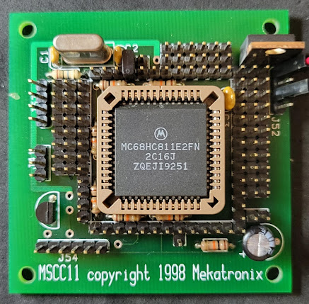
So, I just got this amazing gem of a thing, essentially a breakout board for Motorola HC11 series microcontroller with a special point of note since this particular board already has a controller IC in it, more precisely a MC68HC811E2. This microcontroller was very popular when I first started on my automation and control quest but I never got much exposure to it so know very little (yep, showing my age here).
The guy(s)/ gal(s) that wrote the Wikipedia entry say it best when it comes to quickly describing this family of devices:
"The 68HC11 (6811 or HC11 for short) is an 8-bit microcontroller (µC) family introduced by Motorola in 1984[***]. Now produced by NXP Semiconductors, it descended from the Motorola 6800 microprocessor by way of the 6801. The 68HC11 devices are more powerful and more expensive than the 68HC08 microcontrollers, and are used in automotive applications, barcode readers, hotel card key writers, amateur robotics, and various other embedded systems."
*** I started later than this, I'm not that old.
The text above kind of makes it sound that they are still widely used but even though I did about 0 scientific research on this topic, I very much doubt that. Compared to the current alternatives these are lacking serious features and the only way these are still going to be used is of they are extremely cheap. The NXP product page says that they are "not recommended for new designs" which simultaneously seems to indicate they are still in production (like the Wikipedia entry hinted too) but not for long. If you are starting on the embedded systems path, definitely DO NOT start here, use an Arduino instead. Who am I kidding? Of course you're already doing that.
Anyway I'm looking into this more from the point of view of bringing something old back to life and with today's tools as much as possible. As you will see I managed to interact with the controller with old software running on a current windows 11 machine - the process has its quirks but it works. It wasn't a smooth ride, it took me a while to find the tools that worked. Hopefully I can spare some of your time if you are looking to do something like this and do not know where to start.
Yep, I made this LED blink all by myself.
In this post I will briefly describe the tools I used and the steps I took to connect to the 68HC11 and load programs. The programs I can load are written in assembly. There's no fancy higher level language like C at the moment, but that may come soon as my 007-worthy investigation has shown there are such compilers out there in the wild.
Keep reading if you too would like to blink an LED on a Motorola 68HC11.
What you need
Hardware
Let us start with the most obvious of all and this may come as a shock to you but you will need a microcontroller of the HC11 family. The board I have is as simple as it can get, really, as the only fancy thing that it has other the controller itself plus the crystal and associated circuitry is a 5V regulator including filtering capacitors. Other than that it kind of exposes all the IOs on male headers and that's it.
I needed to know exactly where to power the thing (this was the easiest as I could follow the traces to the power header with no issues). I also needed to know which header was RESET and which headers exposed the MODA and MODB pins. Oh and I almost forgot about the Serial UART Rx and Tx connections. I needed those too. If I could know all of that I would know everything needed on the hardware side. Additionally if I could find a port where to connect an LED and watch it blink through a program of my own, that would be awesome. We all can see I needed the datasheet of this board or I was going to spend quite a lot of time following copper traces and my eyesight is not like before.
It turns out the manufacturer of this board is still around. See the Mekatronix name on the board? Well go to mekatronix.com and enjoy the array of robotics products from the late 90s, early 2000s. This is no joke, they're actually pretty impressive and cool. That was the golden age of amateur robotics and I will risk to say that it was these guys and more like them that created the maker community as we know it now. But I digress. See the "MSCC11" board name? Here's the manual for it I downloaded off their site. It was a lucky break and maybe this was going to be easier then I thought.
There are two key parts on the manual/ datasheet: there's a main circuit schematics and the actual connections layout as you can see below.
The pinout of the board.
Part of the circuit schematics.
All of this was, of course, extremally useful. For example, I can see that the MODA and MODB connections are already pulled up on the board with 10K resistors, so I need not worry about extra circuitry.
I already mentioned MODA and MODB a few times so let me quickly just mention that the 4 state combinations available set the controller into different modes of operations, as follows:
- MODB HIGH, MOD A LOW = Single chip mode (the chip itself and not much else, just like what I have).
- MODB HIGH, MOD A HIGH = Expanded mode (This mode is for setups with external memory. I will not use this).
- MODB LOW, MOD A LOW = Bootstrap mode (I will use this).
- MOD B LOW, MOD A HIGH = Special test (I will not use this as I'm not doing anything special).
For what we are going to achieve under the scope of this post, we will stay on Bootstrap mode all the time (this is me making it simple for you, dear reader. That and I still don't know enough to venture outside of that mode). Looking closely at the datasheet for the board, I see I need to jump the MOD pins to the adjacent pin, which connects to GND. Doing that to both pins puts the controller into bootstrap mode.
The jumped pins look like this. Pretty.
If you now look at the pinout of the board that I posted above, you can see the RESET connection on pin 17. I'm not going to show you but either believe me or check the datasheet and you can see that the RESET pin is already pulled HIGH with a resistor. Convenient, it's like they knew what they were doing. So I can connect the pin to ground every time I want to reset. There's no ground pin near the reset button, but I found another one else where and used a jumper cable like the yellow one above on the MODs picture. I connect it to ground every time I need. I remove the connection for normal operation.
Finally the Rx and Tx pins are available on J51 (see the pinout drawing again. I suggest you enlarge and print that picture we will be coming back to it again and again).
Next on the list of things you will need, you must find a way to connect the serial UART on the controller (the Rx and Tx pins I just mentioned) to a computer. Once upon a time there were some serial 9-pin and 25-pin D connectors that were commonly used to connect to computers. You still needed some kind of level conversion circuitry to be able to connect your PC to a microcontroller. I have the original communications board for the device I'm using. It uses a 25-pin D connector and I have not seen one of those in close to 300 years. Here's a picture of my communications board for science. I will not be using it.
Note the corrosion and dirt although that's not the problem. The problem is the DB25 connector.
As I mentioned, these boards do level conversion and shifting from your PC serial port to the 6811 0 (logic LOW) to 5V (logic HIGH). I will be using my 1020 laptop and it sports a couple of USB ports and that's it. Whatever bits are coming in and out of it will have to use route.
That's easy peasy of course. It just so happens that sometime ago I got myself a slimmed down Arduino board that doesn't have an on-board level shifter chip (the regular "larger" boards have one built-in like the one you can see below). So I had to get a standalone interface board. It turns out I can use it now too! Love it when a non-plan comes together.
The serial converter/ shifter on the Arduino UNO board
Here's a picture of my FTDI-based board in all its converting glory.
Convert it please.
While you're at it, go ahead and connect an LED to port B0 using a current limiting resistor (I used 1K). This will be our blinker.
And all this completes the HW side of the things you will need. Now on to the software. Where's HW, there's SW to go with it.
Software
I spent some time looking for the right software to use on this project but I suspect that anybody else would have spent a lot less time. My stupidity? Maybe, but I won't call it that. You see the thing is that after the first 10 minutes of research, you will find that the original downloader made by Motorola, called PCBug11 is not really useable in modern computers and you should use a variant of that called JBug11. JBug11 is freely downloadable
from here.
When I first tried to download JBug11, my Windows 11 machine gave me all kinds of warnings to say that I shouldn't be doing that. At the time I wasn't 100% sure of what JBug was so I avoided it like the plague. It is also hosted on sourceforge which
has not been reliable as it once was. So I went into a rabbit hole of options that really were never going to solve my problem.
From deep the rabbit hole of the things I saw and tried I ended up using one of them to write and compile my assembly programs (I was originally looking for a downloader but I stumbled across this IDE/ compiler). It's called MiniIDE and you can
get it from here. It looks like this:
It is also a downloader and that is why I came across it but I didn't have good results with the downloader feature. I'm not too sure but it looks like it was made for another development board based on the 6811 so it's kind of geared towards that. It does allow you to write your programs and compiles the code into S19 files which you can then use another downloader to load to the microntroller.
After a while I had everything except the ability to load programs so even though it felt like I could get an STD, I was going to risk it all with JBUG11. And I did it. I got warning after warning but I ignored them all. The installation was ok but I got an error the first time I tried to run it. I thought I was surely already mining bitcoins and I had no more RAM available. That wasn't the case as the second time I tried to run the thing it started with no issues.
It took me a little while to figure out how to use it and I'm still not quite there yet. One of things that would have been really, really helpful was the help menu. The program is pre-historic (not quite but whatever) and it comes with the legacy .hlp windows help files. You can't use those on Windows anymore. I magically managed to extract the help files on to a pdf that you can download from my google drive (link at the bottom). No need to thank me I just like doing God's work for free.
I was at a point where I pretty much had everything needed to make an LED blink. Between tries and retries I did find a way to work with the microcontroller.
Procedure
I started by writing the following program. It took me ages as I wasn't really familiar with the 6811 assembly. Of course I got it from the internet like a boss so I was lying it did not really take me that much time.
PORTB EQU $1004
ORG $0000
START ldaa #$FF
staa PORTB
clra
LOOP inca
cmpa #10 ; T -> decimal
blo WRITE_PORTB
clra
WRITE_PORTB staa PORTB
ldx #60000 ; delay time
next_x1 dex
cpx #0
bne next_x1
BRA LOOP
Put this on miniIDE and compile it (click on the "Build Current" button). That will create a S19 file. This code will output the result of an incremental counter to the whole of port B from 0 to 255 (8 bits). Through the mathematics of binary counting, pin PB0 will flash at a good frequency like a fast heart rate which is what I wanted to see on my "Hello World" effort.
Go to JBUG11, click connect. Ensure the board is on Bootstrap mode (both MOD lines LOW) and reset it. You should see the talker load (the talker is a small program that allows JBUG11 to interact with the controller. You must have this loaded to you can see register values, memory contents and even load programs). A successful talker load procedure looks like this:
After this, click the load S19 file button and find the S19 file you just created. This will load the file to your controller and the LED on PB0 will immediately start blinking, no need for reset (I still have not figured that out, I thought it would need a reset before it starts running, but no. Probably has something to do with the fact that the processor is on that special bootstrap mode).
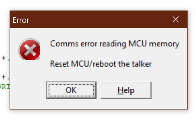
Some things of note: After the steps I just described, JBUG will loose connectivity to the controller. Is it because it lost the talker? I still need to figure that out. Then there's then no f**ing way that I can regain connectivity unless I restart JBUG11 and repeat the process up to the point of loading the S19 file.
I can't tell you how many times I have seen this message, the number is too great.
When I'm in that stage (connected and before loading the program) everything works great, I can see the contents of memory with "L 0" for example.
You can see the talker has been loaded to the first sections of RAM and I can see the first 16 bytes of RAM with the L 0 command. Check the helper file for more commands.
Conclusion
I went from a dusty controller board to a blinking LED, hardly something to write home about but good enough to write a post on my blog. I had a great time learning about this controller. My testbed is built so I think I will continue to push on with doing more breathtaking things like blinking two LEDs instead of just one. Actually I think my next move is hobby servo control using this board because I can see on the Mekatronix webpage that this did control a few servos. I may build something cool with it, keep watching this space. If you have any knowledge about the 68HC11 microcontroller, do share, would love to learn from you.
Tools
For my future self, I host the following files on my google drive in case they ever disappear from their original homes on the internet. This is my service for you and for me.


Comments
SSCs were not common at that time. I wrote a letter to an engineer at NASA Goddard Flight Center who had published an article on a low cost version a few years earlier. He helped me source a hand wound flux gate sensor.
Hands down, it was the coolest project that year.
I probably still have some HC11s in 48 pin dip package in a sleeve with buffalo roms. If you have any interest id send them free of charge.
Eventually we got the Nohau ICE (in-circuit emulator), which had the same CPU, but was a completely different MPU with RAM for IMEM instead of ROM, so liberating.
I did have on-board PROM when I was developing for the HC705 (I think it was the 705J). You heard right, PROM, not EPROM. I was given a tube of 10-20 parts, and told "we can buy more". It was a matter of pride to get it right before I ran out of parts. I have no idea why the EE gave me that set up, it must've been a lack of ceramic parts with an erase window.
I would love to chip in with advice, but that was 25 years ago, so all I can say is have fun with the project.